
SXRX Stainless Steel Bioethanol Burner Sizes and Cutout Planning
A nominal burner size is only a starting point. Match the selected manual burner to its approved drawing before fixing the opening, surround and operating access.
- Author
- Liang Ethan
- Technical lead
- Liang ZhengXiangAll models
- Published and reviewed
On this page

Burner size and cutout. One critical distinction.
The dimension in a product selector is not automatically the dimension your fabricator should cut.
The SXRX manual stainless-steel burner catalogue reference lists seven sizes, from 400 to 1000 mm long. Each is shown as 300 mm wide and 115 mm high. This consistent family makes early visual planning easier—but a nominal product size and a construction opening are two different pieces of information.
Use the catalog dimensions to select and compare. Use the exact manufacturer drawing and installation instructions to fabricate.
The seven manual-burner catalogue sizes
Scroll across the table to see all columns.
| Nominal length | Listed overall size | Reference scope |
|---|---|---|
| 400 mm | 400 × 300 × 115 mm | Manual catalogue reference |
| 500 mm | 500 × 300 × 115 mm | Manual catalogue reference |
| 600 mm | 600 × 300 × 115 mm | Manual catalogue reference |
| 700 mm | 700 × 300 × 115 mm | Manual catalogue reference |
| 800 mm | 800 × 300 × 115 mm | Manual catalogue reference |
| 900 mm | 900 × 300 × 115 mm | Manual catalogue reference |
| 1000 mm | 1000 × 300 × 115 mm | Manual catalogue reference |
These are manual-burner catalogue references. Confirm the selected configuration, availability and current drawing with the quotation.
What to confirm for the selected burner
Scroll across the table to see all columns.
| Planning item | Document or check | Decision it supports |
|---|---|---|
| Model and configuration | Written order: model, length, finish and lid/tool details | Identify the burner being supplied |
| Overall dimensions | Exact product drawing and delivered-unit measurements | Coordinate the product envelope |
| Installation opening | Approved opening drawing, support and clearance requirements | Release the surrounding fabrication |
| Availability and lead time | Current quotation or order confirmation | Plan procurement for the selected configuration |
Confirm availability and lead time when placing the order. For drawing requests, use the technical resources and model-specific support guidance; a catalogue length is not a cutout dimension.
Why the opening may need different information
The product envelope tells you how large the selected insert is. A coordinated opening also has to account for the approved fitting method, manufacturing tolerance, support, non-combustible construction, thermal separation, ventilation and access. None of those should be inferred from the variant title alone.
The confirmed overall dimensions of the selected burner.
The exact opening confirmed by the current drawing.
Clearances and materials required around the appliance.
Space for operation, inspection and future removal.
Choose length as part of a composition
A shorter burner can create a concentrated focal point; a longer one can reinforce a horizontal feature wall. Neither is automatically better. Put the provisional burner length into an elevation with the full surround, margins, furniture and main viewing angles. Then review how the flame line relates to the room rather than selecting by wall width alone.
The current reference listing describes a stainless-steel insert with a mechanical sliding lid and supplied operating tool for manual flame control and shutdown. That operating path needs to remain clear after the stone, metalwork or joinery is installed. Confirm the lid and tool configuration for the selected burner.
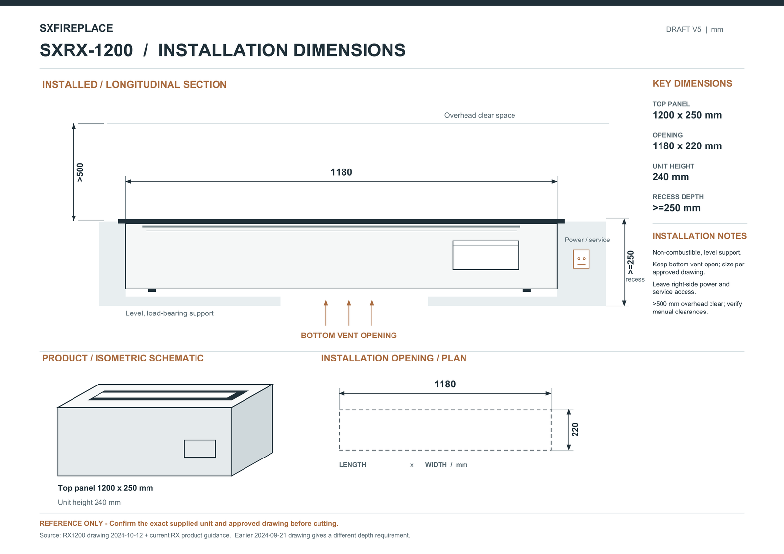
Reference compilation dated 2026-09-25. Confirm the source revision and required depth for the supplied unit.
Open the source PDFSXRX-L-005 Smart installation: use its own body dimensions.
The seven-size manual table above does not specify the SXRX-L-005 smart burner. For RX Smart, record the visible panel, actual body dimensions and installation opening separately. Use the current drawing for the complete ordered configuration.
The RX handbook gives a structural opening reference of body length L2 + 30 mm, body width W2 + 20 mm and depth greater than body height H2 + 20 mm. L2, W2 and H2 are body dimensions, not the nominal length or top plate. Custom assemblies need the approved order drawing; do not apply this formula to the manual table or use it as a fabrication release.
- Keep the right-end power adapter and service connections accessible. The delivered adapter label controls the electrical provision; older ratings are not universal.
- Coordinate the specified bottom ventilation, level non-combustible support, surrounding materials and service access in the enclosure section.
- RX uses on-unit and remote controls, with no Wi-Fi or App connection and no user-adjustable flame levels.
- Draining interfaces vary by size and configuration. Confirm the actual connections and supplied instructions before service.
Review SXRX-L-005 dimensions and supply scope · Open the family manuals · Request a current model drawing
A five-step check before manual-burner fabrication
- Select a provisional burner length based on the overall room composition, then confirm that configuration with SXFireplace.
- Request the current drawing and instructions for that exact variant and any selected customization.
- Have qualified parties confirm support, non-combustible materials, clearances, ventilation and applicable local requirements.
- Confirm safe access for filling, lighting, sliding-lid adjustment, extinguishing and cooldown checks.
- Release the surrounding fabrication only after those points are coordinated.
Size planning is also operating planning
A flush, minimal installation should not make the burner difficult to use. Never refuel while the burner is operating or hot. Follow the exact product manual for approved fuel, lighting, extinguishing, cooldown and ventilation. Do not treat this planning article as a substitute for product-specific instructions or local professional requirements.
At handover, identify the installed model and operating tool, and leave the applicable instructions with the responsible operator. Start with the manual fireplace user guide and confirm its applicability to the delivered model and configuration.
Confirm before you cut
Send SXFireplace the intended variant, surround material and project location so your team can identify the documents and checks required before fabrication.
Use the installation planning guide to coordinate the opening with support, ventilation and access.